I started playing a little with electronics, for the first time in my life. I keep on being amazed with the wide options it all open for me, breaking the PC to small parts unleash worlds of possibilities. I got into several personal projects — when I immediately saw when these options were revealed.
A good friend of mine introduced me to Autodesk Eagle — software to draw circuits. In addition you can download and insall Adafruit & Sparkfun electronics huge parts catalog in your Eagle for you to use.
I bought a ESP32 WROOM DevKitC from Expressif — but couldn’t find the proper Eagle schematics for the ESP32 unit on the web (even after looking for it for a half a day). There were a lot of links that presented the information in .pdf files. Cause it is very early stage of me playing with Eagle, I couldn’t find a proper way importing the .pdf to Eagle.
So I used the following resources:
- Drawing of the schematics of the ESP in .pdf
- Image taken of the ESP unit (which is used as the footprint background image)
And assembled a My Eagle schematics of ESP unit – Download ESP32 DevKitC Eagle Library Schematics.
Due to the fact it is the first day I am playing with Eagle, there may be issues in the Schematics I assembled, which will be corrected if required.
More information about the different kind of ESP units can be found here.
My DoorBell Project:
My doorBell project is easy to explain,. basically some one rings the bell and a whole process it inititiated:
- BellRing event is launched (On the ESP unit)
- Windows Server logs activity (Using Delphi Datasnap WebBroker Technology)
- Windows Server notify Android end units and a RPiZW unit to play the audio ring (Android units written with Delphi FMX, and RPiZ is a python based script)
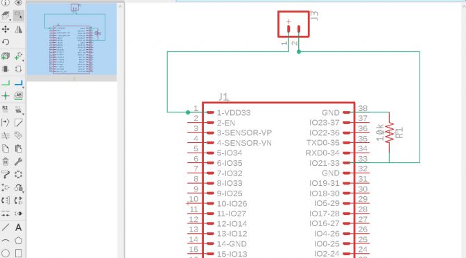
An Eagle schematics I made of the ESP32. The big chip in the middle is the ESP32 v4 I am using:

I added in, the Eagle footprint image of the chip as noted:

This is a sample of the unit in action (on a test breadboard — note it is wired differently — it is the first test I made), with all sides modifications — it still requires some modifications and changes:
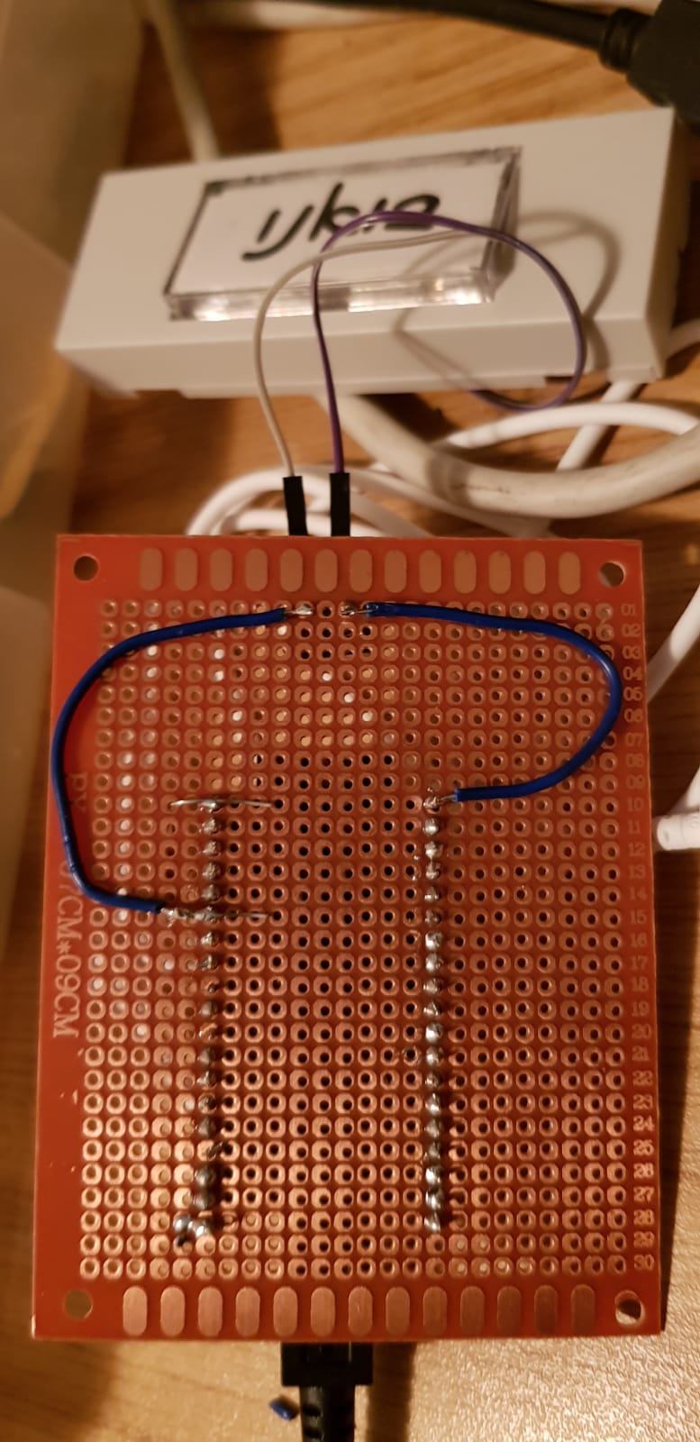
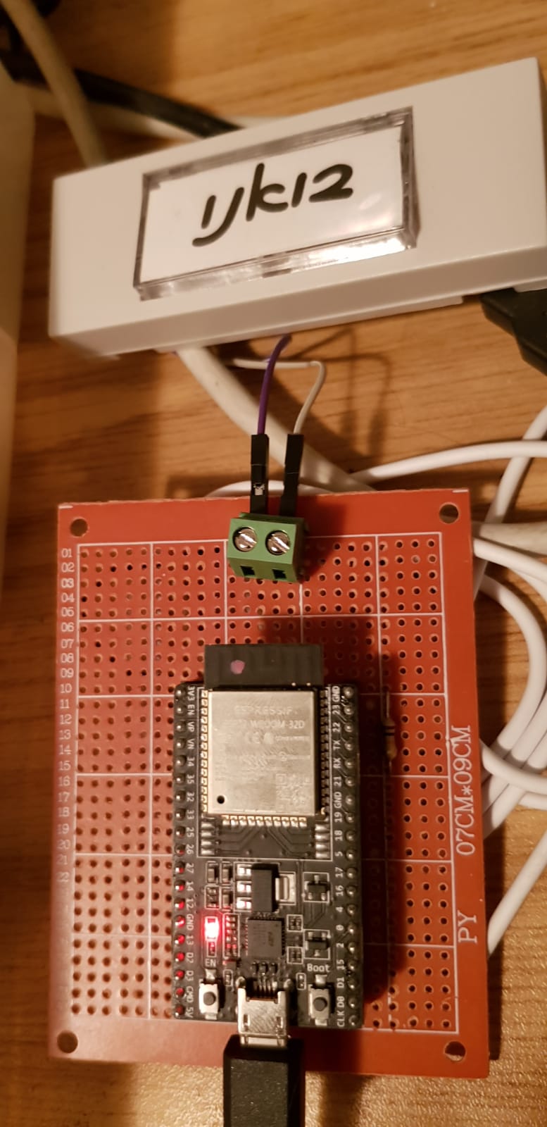
This is are two images of the circuit soldered on a standard prototype board: